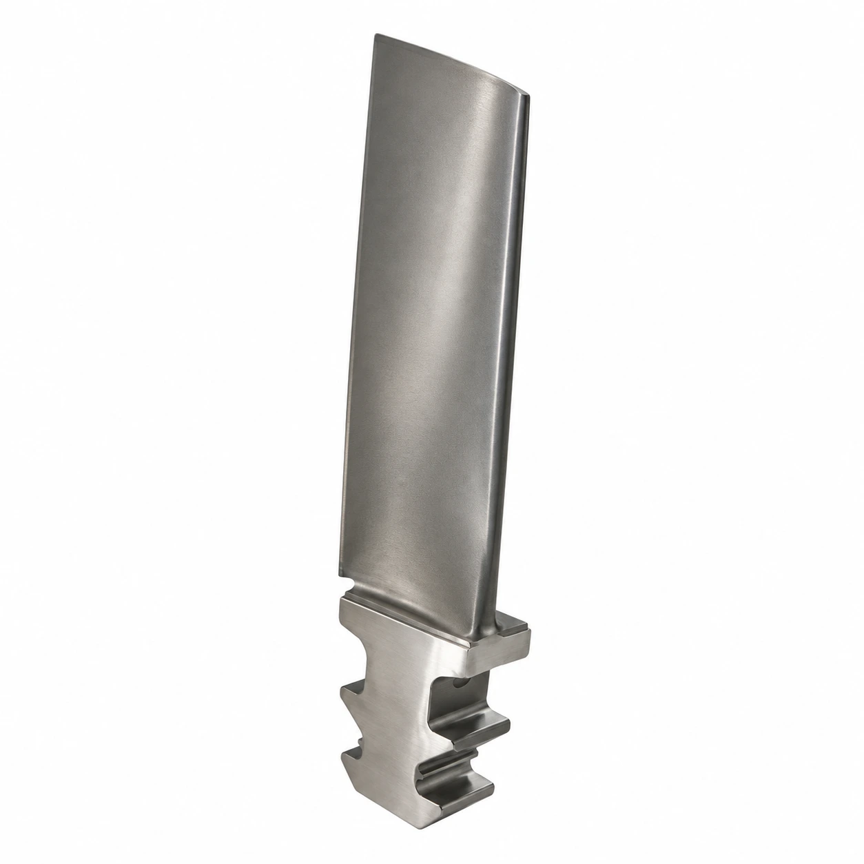
ForceBeyond manufactures custom directionally solidified (DS) turbine blade castings
for aerospace and industrial gas turbine programs through its manufacturing
network. The service combines specified columnar grain growth with airfoil,
platform, root and, where required, internal cooling geometry. We coordinate
casting, applicable heat treatment, inspection and precision machining for the
agreed casting-only or finished-blade scope.
ForceBeyond can define a DS blade manufacturing package from the specified casting blank through inspected, machined or finished airfoil delivery. The quotation identifies the approved grain direction, cooling features, root and platform interfaces, downstream operations and release records for that blade design.
Request a custom DS blade quote. Send the drawing revision, exact alloy,
specified grain direction, cooling geometry and inspection requirements.
Request a custom quote.
Tier 1.5 Turbine Blade Supply: From Casting to Finished Airfoil
ForceBeyond's Tier 1.5 model brings DS blade casting, downstream processing and release
planning into one supply program. Co-owned manufacturing resources support direct
operational oversight. Our U.S.-based team coordinates drawings, commercial scope
and engineering communication across selected resources in the USA, South Korea and
Taiwan network, giving OEM procurement teams one point of contact.
For a finished airfoil, we plan the handoff from controlled casting to grain and
soundness inspection, heat treatment, root and platform machining, cooling-feature
verification and any specified coating or finishing. Material, process and inspection
records follow the agreed release package. This integrated supply scope makes
interfaces between specialist operations explicit without assuming every operation
occurs at one facility.
Custom DS Turbine Blade Manufacturing Services
ForceBeyond supplies nickel-based superalloy DS blade castings with the specified airfoil,
platform and root attachment geometry. Tooling, ceramic cores for internal passages,
controlled directional solidification, prescribed heat treatment, grain and soundness
inspection, NDT, root and platform CNC machining, and coating or finishing can be
coordinated as the approved scope requires.
A casting blank and a machined or finished blade have different acceptance stages. Our
manufacturing review defines which geometry is controlled in the casting, which
interfaces are machined and when cooling passages, dimensions and grain structure
are verified. For OEM buyers evaluating a DS blade manufacturer or supplier, that
defined scope makes the quoted product and release evidence clear.
Gas turbine and aerospace blade applications
Selected turbine stages may specify a DS blade when a controlled grain direction is part
of the material and life assessment. Industrial gas turbine and aerospace engine designs
differ in duty cycle, cooling, coating and acceptance documentation. The actual stage and
approved material definition govern the scope, not the label “DS blade” alone.
Columnar grains, load direction and thermal exposure
DS processing aligns columnar grains primarily along the intended growth direction,
reducing transverse boundaries relative to a conventional equiaxed structure.
Longitudinal boundaries remain. Creep and thermal-fatigue response also depends on alloy,
temperature and stress cycle, blade geometry and environmental protection; no general
structure comparison is a blade-life prediction.
Select the exact DS superalloy variant
A published NASA DS blade program
used Mar-M 247. René 80 variants and CM 247 LC may also
arise in alloy and route discussions, but their chemistry and processing conditions must
be verified against the actual specification. Similar names do not establish
interchangeable DS castings. The RFQ should carry the complete grade designation,
required grain condition and heat-treatment state.
Cooling, root attachment and final blade geometry
The airfoil profile and cooling passages must be evaluated together: core displacement
or outlet changes can affect local wall thickness even if the outer contour looks
acceptable. Platform, root contact surfaces, fillets and tip features establish the
installed relationship to the disc. Machining, coating and inspection sequence should be
specified so the final delivered state is measurable.
Solid and cooled airfoils need different evidence
A solid airfoil avoids core-defined passage acceptance, while an internally cooled blade
needs evidence for the passage path, outlet position and minimum walls required by its
drawing. Neither configuration can be inferred from the phrase “DS blade.” The blade
model and agreed inspection sequence should state which features are checked before and
after coating or final machining.
Manufacturing and inspection package
A blade program can include tooling and cores, casting and grain control, thermal
processing, finishing, coating and release. The inspection plan may distinguish grain
direction and defects, casting soundness, passage continuity, wall thickness, root
geometry and finished dimensions. Methods and limits follow the governing drawing,
approved processors and acceptance plan.
Grain examination, soundness testing and dimensional metrology answer separate questions.
A blade can meet its external profile while missing the specified growth direction or
cooling-wall condition. The release package should identify the inspection stage,
acceptance standard, measured datums and any approved repair history for each requirement.
DS and SX turbine blades require different evidence
A DS blade retains aligned columnar grains; single
crystal casting adds grain selection or seeding to continue one crystal. The
CMSX-4 blade page addresses an
alloy-specific SX application. For a broader three-way explanation, read the
casting-structure
comparison guide. Neither route substitutes for the other without design approval.
What to include in a DS blade RFQ
Inputs needed to define a DS blade supply package
RFQ input
Why it matters
Drawing and model revision
Defines airfoil, root, platform, tip and cooling geometry.
Alloy and DS specification
Defines exact chemistry, grain structure, growth direction and thermal condition.
Inspection and acceptance plan
Defines grain, soundness, passage, dimension and record requirements.
Cooling and coating definition
Identifies solid or core-defined airfoil features, outlets, wall checks and measurement state.
Delivery state and quantity
Separates casting-only from machined, coated and fully released parts.
For adjacent alloy and process choices, use the turbine
blade and superalloy casting
capability pages. Include the intended stage and operating environment so the
proposal can identify which design and supply assumptions still need confirmation.
Frequently Asked Questions
Does ForceBeyond supply custom directionally solidified turbine blades?
Yes. ForceBeyond supplies custom DS turbine blade castings through its manufacturing network and can coordinate heat treatment, inspection, precision machining and finishing for the agreed scope. Send the drawing, alloy, grain requirements and delivery state for a quote.
What must a DS turbine blade drawing specify?
The enquiry should identify the exact alloy and required columnar structure, grain direction and acceptance criteria, cooling and attachment geometry, inspection requirements and delivery state.
Can a DS blade be replaced with an SX blade by changing the purchase description?
No. The structures and orientation controls differ. A change of route requires the applicable design and material specification to be revised or approved by the responsible authority.
Can a DS turbine blade be ordered as a casting only?
Yes, if the order defines the casting condition, heat treatment and inspection records supplied, and which machining, coating and final-release operations remain downstream.
What changes when a DS blade has cooling passages?
The model and acceptance plan must address core location, passage continuity, local wall thickness and outlet condition in addition to the external airfoil and required grain direction.
Why must the growth direction be related to blade datums?
The intended columnar axis must be assessed against the blade geometry and principal loading. The drawing or approved specification sets the permitted alignment and examination method.
Request a Custom DS Turbine Blade Quote
Send the blade model and drawing revision, exact alloy and DS structure, growth direction, cooling details, inspection criteria, quantity and casting or finished-blade scope.